How does it work?
How does ARINC 818 work?
ARINC 818 protocol, the Avionics Digital Video Bus (ADVB), is based on Fibre Channel Audio Video (FC-AV) and ANSI INCITS 356-2002.
Benefits of ARINC 818
A key benefit of ARINC 818 is low overhead, which allows real-time transmission of video signals at high data rates—Up to 28 Gbps as of 2019, with prospects for higher speeds in the future.
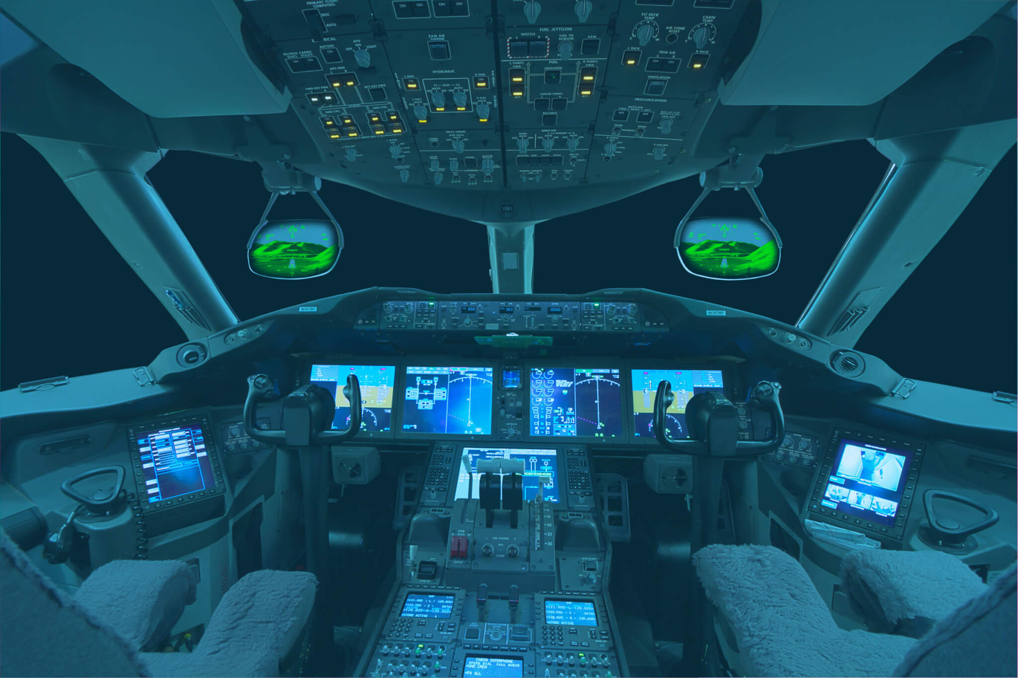
The protocol has very low latency, which amongst other suitability, ensures that a head-up display matches a pilot’s visual input.
ARINC 818 allows great flexibility. By utilizing an interface control document (ICD) to maintain interoperability among the components of a particular ARINC 818 system, the protocol is not tied to any one physical layer or video format. On fiber, video can be transported over long distances (limited to 500 meters to 10 kilometers, depending) with no electromagnetic interference.
It can also be utilized on copper, including bidirectional coax. Other physical layers, such as wireless, are unproven but likely possible.
ARINC 818 protocol converts each video frame into a transport unit called an ADVB container. Within the container are packets called ADVB frames. Because ADVB frames do not correspond one-to-one to video frames, it is important to avoid referring simply to « frames ».
Containers & frames
Transmission process
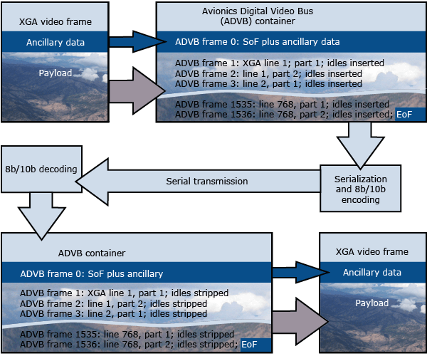
In avionics, typically, the source of the video frame is a graphics generator or mission processor and the target is a display unit. Transmission involves these steps:
- Video packaged into ADVB frames, with idles added to accommodate timing;
- Serialization and 8-bit/10-bit (8b/10b) encoding;
- Serial transmission;
- 8b/10b decoding;
- Reconstruction, including the stripping of idles.
Eight-bit/10-bit (8b/10b) encoding allows for long-distance transport. For every 8 bits (every 1 byte) of information sent, the physical link transmits 10 bits, which adds 20 percent overhead on the physical link. For example, to transmit 32 bits (4 bytes), the 8b/10b encoding will physically transmit 40 bits over the link. The 4 bytes will be stripped back down to 32 bits once it has been received. Bytes are designated as data or special characters, such a start of frame (SoF), end of frame (EoF), and idle characters. When data is not being transmitted over the physical link, idle characters will be inserted, maintaining continuous transmission.
The container consists of a header and objects known as the payload. The simple parametric digital video profile uses four objects for encapsulating the ancillary data, audio data, and video data. The payload from the whole sequence of ADVB frames is a container. A container is assembled from the payload of many ADVB frames.
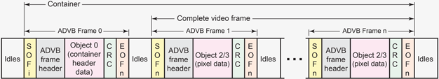
The payload of the first ADVB frame transmitted contains Object 0, or the container header, which includes ancillary data. The payload of the next ADVB frame contains the first lines of video data, in Object 2. The payload often contains only Object 0 and Object 2. Object 1 is for audio that usually is not used, and Object 3 is used only in the case of interlaced video frames.
Interface Control Document
ARINC 818 implementations are compatible only when they share an interface control document (ICD). Therefore, implementations must always be associated with ICDs. Among the basic features set out by the ICD are:
- video resolution;
- scan type;
- frame rate;
- pixel format.
Characteristics for more complex systems are also covered.
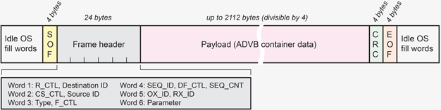
ADVB frame structure
Idle words: Idle ordered sets are transmitted between ADVB frames. Typically, a minimum of six idle ordered sets between each Fibre Channel frame is needed. When transmitting, the number of idle ordered sets between ADVB frames can be varied to adjust the video frame time (to adjust the horizontal blanking).
Start of frame: ARINC 818 is independent of class of service. Currently, Class 1 and Class 3 implementations exist.
Data payloads: The first frame of an ADVB container data sequence includes the container header and Object 0 ancillary data as its data payload. Subsequent frames of the container sequence include the Object 2 video pixel data. Each is limited to 2112 bytes, which may require a single line of video to be broken into multiple ADVB frames. In the XGA example, each of the 1024 RGB pixels in a line requires three bytes (3072 bytes per line), so a video line must be divided between two 2112-byte ADVB frames.
Cyclic Redundancy Check (CRC): After a video frame has been transmitted, a 4-byte CRC for error checking follows. It uses the following 32-bit polynomial:
X32 + X26 + X23 + X22 + X16 + X12 + X11 + X10 + X8 + X7 + X5 + X4 + X2 + X + 1
End of frame: All frames except the last frame of an ADVB container data transfer sequence use the End of Frame Normal (EOFn) ordered set, beginning RD Negative or RD Positive.
The last frame of an FC-AV container data transfer sequence uses the End of Frame Terminate (EOFt) ordered set, beginning RD Negative or RD Positive.
Since the adoption of ARINC 818 more than a decade ago, custom implementations have led to a revised standard capable of such things as switching, data-only return paths (for control of sensor pods, for example), and regions of interest frames rates higher than the rest of the frame. Higher ARINC 818 link rates, currently up to 28.05 gigabits per second, are already in place to take advantage of faster FPGAs of tomorrow.